How to Read HVAC Wiring Diagrams: Ladder Schematics, Pictorials and Symbols
The diagram glued inside the panel is the fastest way to understand a unit you've never seen. You don't need to memorize every manufacturer's drawing style; you need to know how to find the rung that isn't working.
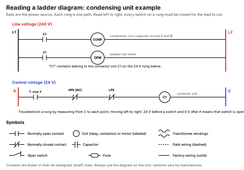
The two kinds of diagram
Most equipment shows both:
- Ladder (schematic) diagram: the circuit logic. Power is drawn as two vertical rails and each load sits on its own horizontal rung. This is the one you troubleshoot with.
- Pictorial (connection) diagram: where parts actually sit in the cabinet and which terminal each wire lands on. Use it to find the part once the ladder diagram tells you which one to check.
HVAC School's advice: look at the whole diagram first, especially the legend and notes, before you start tracing.
Rules that apply to almost every diagram
- Rails are the source. Line-voltage sections show L1 and L2 (or L1, L2, L3). Control sections show the transformer's R (hot) and C (common).
- Loads go on the right, switches on the left. A rung reads left to right: from the hot rail, through switches and contacts, to a load (motor, coil, heater, gas valve), to the other rail.
- Series means AND. Every switch in series on a rung must be closed. Two switches drawn in parallel are OR: either one closes the path.
- Shelf state. Contacts and switches are drawn de-energized, as if the part were sitting on a shelf: normally open (NO) contacts drawn open, normally closed (NC) drawn closed.
- Coils and their contacts are separated. The contactor coil sits on a 24 V rung; its contacts appear on the line-voltage rungs with the same label (C1, CR, K1). Find the coil to know what closes those contacts.
- Solid vs. dashed lines. Factory wiring is usually solid; field wiring (thermostat wire, power supply) is usually dashed.
- Component codes. The legend maps abbreviations: HPS (high-pressure switch), LPS (low-pressure switch), CR (control relay), OFM (outdoor fan motor), IFM (indoor fan motor), RVS (reversing valve solenoid), CCH (crankcase heater).
Tracing a dead rung with a meter
Example: the thermostat calls for cooling and the contactor won't pull in.
- Find the contactor coil rung on the 24 V ladder.
- Put one meter lead on the C rail (common) and leave it there.
- Touch the other lead to each point on the rung, starting at R and moving right: before and after the thermostat Y contact, before and after each pressure switch, then at the coil.
- You'll read 24 V until you cross the open component; after it, 0 V. That component is your problem (or the wire between).
- If you have 24 V right up to the coil and it still won't pull in, the coil is bad: see how to test a contactor.
The same method works on line-voltage rungs, with the right PPE and a meter rated for the voltage. Measure across a switch to see whether it's open: full voltage across a switch means it's open; near zero means it's closed.
What to look for on furnace and heat pump diagrams
- Furnace safeties (limit, rollout, pressure switch) are wired in series in the gas valve or control circuit. An open one stops ignition: see furnace gas valve not opening.
- Board-based equipment shows the control board as a box with terminals. You can't trace inside it, but you can check every input and output at the board.
- Heat pumps add the reversing valve solenoid, defrost board and outdoor sensors: see reversing valve troubleshooting.
- Notes often say things like "replace wire with same type and temperature rating" or which taps to use for 208 V. Read them.
Thermostat wiring
Low-voltage terminal letters (R, C, Y, W, G, O/B) are covered in thermostat wiring terminals and colors.
FAQ
What's the difference between a schematic and a wiring diagram?
The schematic (ladder) shows how the circuit works. The wiring (pictorial or connection) diagram shows where the parts and wires physically are. Troubleshoot on the schematic, then find the part on the pictorial.
Why do contacts look open on the diagram when the unit is running?
Diagrams show contacts in their de-energized shelf state. A contactor's NO contacts are drawn open even though they're closed while the unit runs.
What do dashed lines mean?
Usually field wiring, installed by the contractor, such as thermostat wire or the power supply. Solid lines are factory wiring.
Where do I measure to find an open switch?
Keep one lead on the return rail (C for 24 V) and move the other along the rung. The point where voltage disappears is just past the open component.
Sources
One field tip a week
A short, practical HVAC tip in your inbox every week: diagnostics, charging, airflow and code changes. Free, unsubscribe anytime.
We'll only use your email for the newsletter. Privacy policy.
Related guides
How to Test an HVAC Transformer: 24-Volt Checks, VA Rating and Shorts
How to test the 24-volt control transformer in a furnace or air handler, how to size a replacement by VA, and how to find the short that killed the last one.
How to Test an AC Contactor: Coil, Contacts and Voltage Drop
Test a condenser contactor the right way, from 24 V at the coil and coil resistance to pitted contacts and voltage drop under load.
Thermostat Blank or No Power: Finding the Missing 24 Volts
How to troubleshoot a blank thermostat: batteries, the C wire, the furnace door switch, a blown board fuse, a tripped float switch, the transformer and power to the air handler.
Thermostat Wiring: Terminal Letters and Wire Colors Explained
What each thermostat terminal does (R, Rc, Rh, C, W, W2, Y, Y2, G, O/B, E, AUX), the usual wire colors, and how to verify a hookup.
Field reference for trained technicians. Always follow the equipment manufacturer's instructions, local code and safe work practices. See our editorial standards, or report a correction.