Mini-Split Communication Errors: How to Troubleshoot Indoor-to-Outdoor Faults
Every mini-split brand has its own code for "the indoor and outdoor units can't talk" (often shown as an E, U or CH code). The causes are almost always the same.
How mini-split communication works
On most ductless systems, a 3- or 4-conductor interconnect cable carries power and a communication signal between the units. Terminals are typically labeled 1, 2, 3 (sometimes with S for signal, or L, N, S) plus ground. The signal often rides on the same voltage as the power wires, which is why wiring mistakes cause communication faults.
Safety: On many systems the communication wire carries line voltage. Lock out, verify dead, and follow the manufacturer's test procedure.
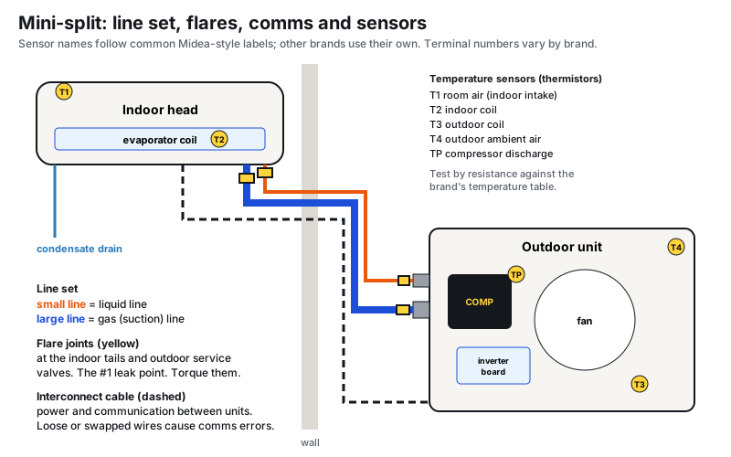
Step-by-step
- Read the exact code from the indoor display, remote or outdoor board, and look it up in that model's service manual. Some codes separate "no communication at startup" from "lost communication while running."
- Confirm power at the outdoor unit and that the indoor unit receives it, if it's powered from the outdoor unit.
- Check the interconnect, terminal by terminal:
- 1 to 1, 2 to 2, 3 to 3 at both ends. Swapped wires are the #1 install error.
- Every screw tight. Gently tug each conductor.
- No splices, or splices made properly and protected from moisture.
- Cable type and gauge as the manufacturer specifies. Many require stranded cable with a specific gauge, and some don't allow shared conductors.
- Ground connected at both ends.
- Measure at the communication terminal per the service manual. Many brands specify a fluctuating DC voltage on the signal terminal when communicating normally. A steady 0 or a steady voltage helps point to which side isn't sending.
- Look for interference: communication wiring run alongside other line-voltage circuits, or a nearby VFD, can disrupt the signal on some systems.
- Check boards and fuses: look for burnt traces, blown fuses or water damage on the indoor or outdoor board. A lightning strike or surge often takes out a communication circuit.
- Multi-zone systems: confirm each indoor unit is wired to the correct port. Many systems run a wiring or piping check mode to confirm.
Before you replace a board
Rule out wiring completely. A board replaced because of a loose terminal comes back with the same code. Some manufacturers offer a jumper or test mode to separate an indoor-board failure from an outdoor one. Use it.
Patterns that narrow it down
| Symptom | Likely cause |
|---|---|
| Comms error right after a new install | Wiring: swapped terminals, wrong cable, loose screw, or a wiring mismatch on a multi-zone port |
| Worked for years, then comms error after a storm | Surge damage to the indoor or outdoor communication circuit, or a blown fuse on a board |
| Comms error only in rain or high humidity | Water in a splice, terminal block or disconnect; corroded terminals |
| Comms error comes and goes, worse when it's cold | Loose terminal or a cracked conductor flexing with temperature |
| Outdoor unit has no power or no board LED | Not a comms fault: fix the power supply first |
| One head on a multi-zone shows the error, others fine | That head's interconnect or its port on the outdoor board |
Test the cable itself
With power off and the cable disconnected at both ends:
- Continuity on each conductor: short two conductors together at one end and measure at the other. Repeat for each pair. Every conductor should show continuity.
- Insulation: each conductor to ground and to the others should read open. A low reading means damaged insulation, often where the cable passes through the wall or a sharp edge.
- Swap test on a multi-zone: move a working head's interconnect to the problem port (if the manufacturer allows). If the error follows the head, the problem is the head or its cable; if it stays with the port, it's the outdoor board.
Common mistakes
- Using thermostat wire or solid low-voltage cable where the manufacturer calls for a specific gauge of stranded cable rated for line voltage.
- Splicing in the line set cover or wall with tape or unsealed wire nuts. Moisture gets in and causes intermittent faults.
- Wiring 1-2-3 correctly but mixing polarity at the outdoor disconnect, which matters on some brands.
- Not tightening terminal screws after the inspector or another trade opened the cover.
- Replacing the indoor board first. On many systems, the outdoor board drives the communication power, so a dead outdoor communication circuit makes every head show an error.
After the repair
Cycle the system off and on at the breaker, run each head in cooling and heating, and check that no codes are stored. On multi-zone systems, run the manufacturer's wiring or piping check mode if it has one.
FAQ
What causes a mini-split communication error?
Usually wiring: loose terminals, wires in the wrong terminals, the wrong cable, bad splices or a missing ground. Less often, a failed indoor or outdoor control board.
Can I use any cable for the interconnect?
No. Use the conductor count, gauge and type the manufacturer specifies. The wrong cable is a common cause of intermittent communication faults.
Why does the error only happen sometimes?
Intermittent faults point to a loose connection, moisture in a splice, or interference from nearby wiring. Check terminals and splices first.
Sources
One field tip a week
A short, practical HVAC tip in your inbox every week: diagnostics, charging, airflow and code changes. Free, unsubscribe anytime.
We'll only use your email for the newsletter. Privacy policy.
Tools for this job
Related guides
Mini-Split Not Cooling or Heating: A Diagnostic Order for Ductless Systems
How to troubleshoot a ductless mini-split that runs but won't cool or heat: error codes, mode and remote settings, filters and blower wheels, the outdoor unit, sensors, communication and charge.
Working Safely on Mini-Split Inverter Boards
Why mini-split inverter boards stay dangerous after power-off, how to verify the DC bus is discharged, and how to approach IPM, voltage and compressor drive error codes.
How to Test a Mini-Split Thermistor (Temperature Sensor)
Test a mini-split room, coil, discharge or outdoor temperature sensor with an ohmmeter and the manufacturer's resistance table, and find out whether the sensor, wiring or board is bad.
How to Clean a Mini-Split: Filters, Coil, Blower Wheel and Drain
How to deep clean a ductless mini-split indoor unit, including the coil, blower wheel and drain, plus the outdoor unit, with the right tools and without damaging the electronics.
Field reference for trained technicians. Always follow the equipment manufacturer's instructions, local code and safe work practices. See our editorial standards, or report a correction.