How to Test a Mini-Split Thermistor (Temperature Sensor)
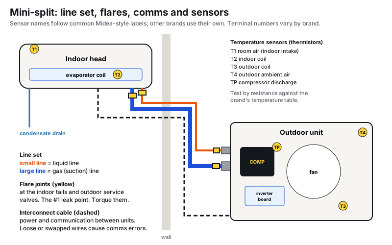
Sensor faults are some of the most common mini-split error codes: room air, indoor coil, outdoor coil, outdoor ambient and compressor discharge sensors all report to the boards. Most are NTC thermistors, meaning their resistance drops as temperature rises.
Safety: Turn off power at the disconnect before unplugging sensors. On outdoor units, wait for the inverter capacitors to discharge (see working safely on inverter boards).
Common codes that point here
Each brand names its sensors differently, so check the code chart for the unit:
- Midea-platform units (Senville, MRCOOL): T1 room, T2 indoor coil, T3 outdoor coil, T4 outdoor ambient, TP discharge.
- Gree: F1 indoor ambient, F2 indoor evaporator, F3 outdoor ambient, F4 outdoor condenser, F5 discharge.
- Daikin: C4, C9, H9, J3, J6.
- Mitsubishi MSZ-GL: 1 blink (room), 2 blinks (indoor coil).
See the mini-split error code lookup.
Step 1: Find the right resistance table
Thermistors come in different values (5k, 10k, 15k, 20k and 50k ohms at 77°F are all used), and the same unit can use different values for different sensors. The service manual has a table of resistance at each temperature for every sensor. Don't guess from another brand's table.
Step 2: Measure
- Power off and unplug the sensor's connector from the board.
- Measure resistance across the two connector pins.
- Measure the actual temperature at the sensor bulb (or let it sit at room temperature and measure the air).
- Compare with the table.
What the reading tells you
- Open / OL: broken sensor or wire. Replace the sensor.
- Near 0 ohms: shorted sensor or pinched wire. Replace.
- Far off the table: failing sensor. Replace.
- Matches the table: the sensor is probably fine. Check the connector for corrosion or a loose pin, then the board.
Step 3: Check the wire and the mounting
Wiggle the lead while watching the meter; a reading that jumps means a broken conductor inside the jacket. Coil sensors must be clipped tightly in their well or on the pipe; a loose sensor reads wrong even when it's good.
Step 4: Board check
With the sensor plugged in and power on, many boards put a low DC reference voltage on the sensor circuit. If a good sensor is installed and the code persists after a power reset, the board's sensor input is the likely problem.
Reading thermistor values
Most mini-split thermistors are NTC (negative temperature coefficient) sensors: resistance goes down as temperature goes up. Common room and coil sensors are often rated around 10 kΩ or 20 kΩ at 77°F (25°C), and discharge sensors are often around 50 kΩ at 77°F, but always use the table for that model.
| What you read | What it means |
|---|---|
| Close to the table value for the temperature you measured | Sensor is good |
| Far off the table (more than about 10–15%) | Sensor drifting; replace |
| OL / infinite | Open sensor or broken wire |
| Near 0 Ω | Shorted sensor or pinched wire |
| Changes erratically when you wiggle the lead | Damaged wire or connector |
Make the test meaningful
- Measure the actual temperature at the sensor with a thermometer or thermocouple, then look up the expected resistance. A sensor that reads perfectly at room temperature can still be wrong on the coil.
- Test at two temperatures. Warm the sensor in your hand or a cup of water (protect the connector) and confirm the resistance drops smoothly.
- Check the voltage at the board with the sensor plugged in, if the service manual lists it. Some manuals give expected voltage at the connector by temperature.
Where each sensor lives and what it affects
- Room (T1): controls when the compressor ramps up and down. A bad one causes over- or under-cooling.
- Indoor coil (T2): freeze protection in cooling, anti-cold-air and overheating protection in heating.
- Outdoor coil (T3): defrost decisions and condenser high-temperature protection.
- Outdoor ambient (T4): sets operating limits and compressor speed ranges.
- Discharge (TP): protects the compressor from overheating. A bad TP sensor can trigger false high-discharge-temperature shutdowns.
Common mistakes
- Testing with the sensor plugged in. Unplug it first, or you'll read the board in parallel.
- Using a generic 10 kΩ chart for every brand. Curves differ.
- Missing the clip. A sensor that's loose on its tube reads air temperature, not pipe temperature, and causes bad control without any error code. Re-seat it and insulate it if the original was insulated.
- Replacing the board for a sensor code without checking the sensor and its harness.
FAQ
Can I swap a sensor from another unit?
Only if the part number and resistance curve match. A wrong value makes the board misread temperature without throwing a code.
Why does the code come and go?
Usually a loose connector, a cracked lead that opens with temperature or movement, or moisture at the connector.
Sources
One field tip a week
A short, practical HVAC tip in your inbox every week: diagnostics, charging, airflow and code changes. Free, unsubscribe anytime.
We'll only use your email for the newsletter. Privacy policy.
Related guides
Mini-Split Not Cooling or Heating: A Diagnostic Order for Ductless Systems
How to troubleshoot a ductless mini-split that runs but won't cool or heat: error codes, mode and remote settings, filters and blower wheels, the outdoor unit, sensors, communication and charge.
How to Clean a Mini-Split: Filters, Coil, Blower Wheel and Drain
How to deep clean a ductless mini-split indoor unit, including the coil, blower wheel and drain, plus the outdoor unit, with the right tools and without damaging the electronics.
Mini-Split Communication Errors: How to Troubleshoot Indoor-to-Outdoor Faults
A step-by-step approach to mini-split communication faults between the indoor and outdoor units, covering wiring, polarity, voltage and boards.
Working Safely on Mini-Split Inverter Boards
Why mini-split inverter boards stay dangerous after power-off, how to verify the DC bus is discharged, and how to approach IPM, voltage and compressor drive error codes.
Field reference for trained technicians. Always follow the equipment manufacturer's instructions, local code and safe work practices. See our editorial standards, or report a correction.